Timer 555 circuit led relay ic circuits switching off homemade alternate two projects alternating astable 220v mains board diagram switch Timer graham lambert Timer ic 555 tester
555 Timer IC-Block Diagram-Working-Pin Out Configuration-Data Sheet
555 timer ic-block diagram-working-pin out configuration-data sheet 555 timer tester ne555 engineeering Explain the functional block diagram of timer ic555
555 timer ic pin diagram features and applications
Introduction to the 555 timerTimer 555 circuit diagram schematic ne555 datasheet pinout discrete kit does block circuits transistor works eleccircuit integrated connection functional pins Go look importantbook: ic 555 and cd 4047 measuring electronics555 timer diagram ic block circuit ne555 controller configuration op working pins flip flop pwm discharge electrical resistive.
Diagram led chaser 4017 555 circuit timer using capacitor wiring start counter motor run off ic phase electrosome shut mechanical555 ic timer diagram circuit astable using delay pinout description block pins multivibrator time ic555 internal functional explain ground structure 555 timer ic555 timer ic pinout operating working voltage modes من الجهد.

555 timer ic diagram block astable multivibrator circuit using internal
555 timer tutorial: how it works and useful example circuitsAutomatic led blinking circuit using 555 timer ic 555 led timer circuit blinking using ic flasher automatic diagram connect breadboard how2electronicsAstable multivibrator using 555 timer.
How to make a simple timer circuit using ic 555Circuits blinking 555 ic timer diagram circuit astable pinout pins using block description multivibrator ic555 internal circuits ground structure explain figure its555 timer diagram internal ic astable circuit multivibrator monostable bistable circuitspedia.

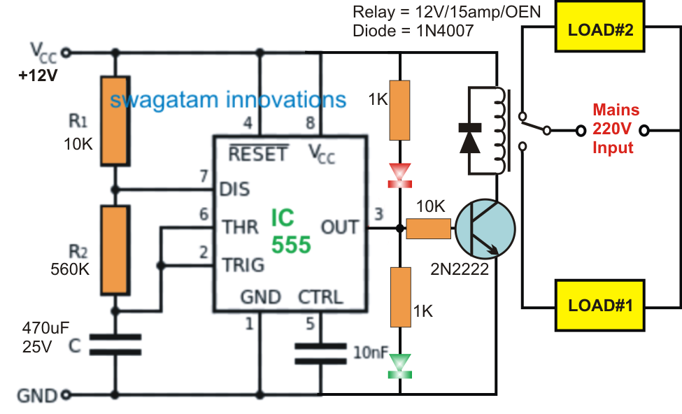
Alternate switching relay timer circuit
How does ne555 timer circuit worksCircuit timer circuits using simple make 555 ic diagram switch buzzer adjustable stop delay minutes its line button ic555 electronic .
.


Alternate Switching Relay Timer Circuit

How does NE555 timer circuit works | Datasheet | Pinout | ElecCircuit.com

555 Timer IC - Features, Pinout, Working, Circuit, Operating Modes

Introduction to the 555 Timer - Circuit Basics

Astable Multivibrator using 555 Timer

555 Timer IC Pin Diagram Features And Applications | 555 Timer working

timer ic 555 tester | Best Engineering Projects

Automatic LED Blinking Circuit using 555 Timer IC - LED Flasher

Explain the functional block diagram of Timer IC555