555 timer circuit circuits ic diagram testing supply power input ends 15v 1x2 1x1 terminals provided must between Timer ic 555 tester 555 timer circuits
timer ic 555 tester | Best Engineering Projects
Dancing light using 555 timer 555 timer tester ne555 engineeering 555 timer circuit using light dancing circuits diagram chip pcb easyeda 555timer pulse ne555 projects lm555 time astable cloud software
Simple motion detector using ne555 timer circuit
555 timer circuit using light dancing circuits diagram easyeda pcb chip based cloud software 555timer pulse ne555 projects lm555 timeMotion circuit ne555 detector using timer simple diagram electronics projects electronic circuits fig applications security .
.

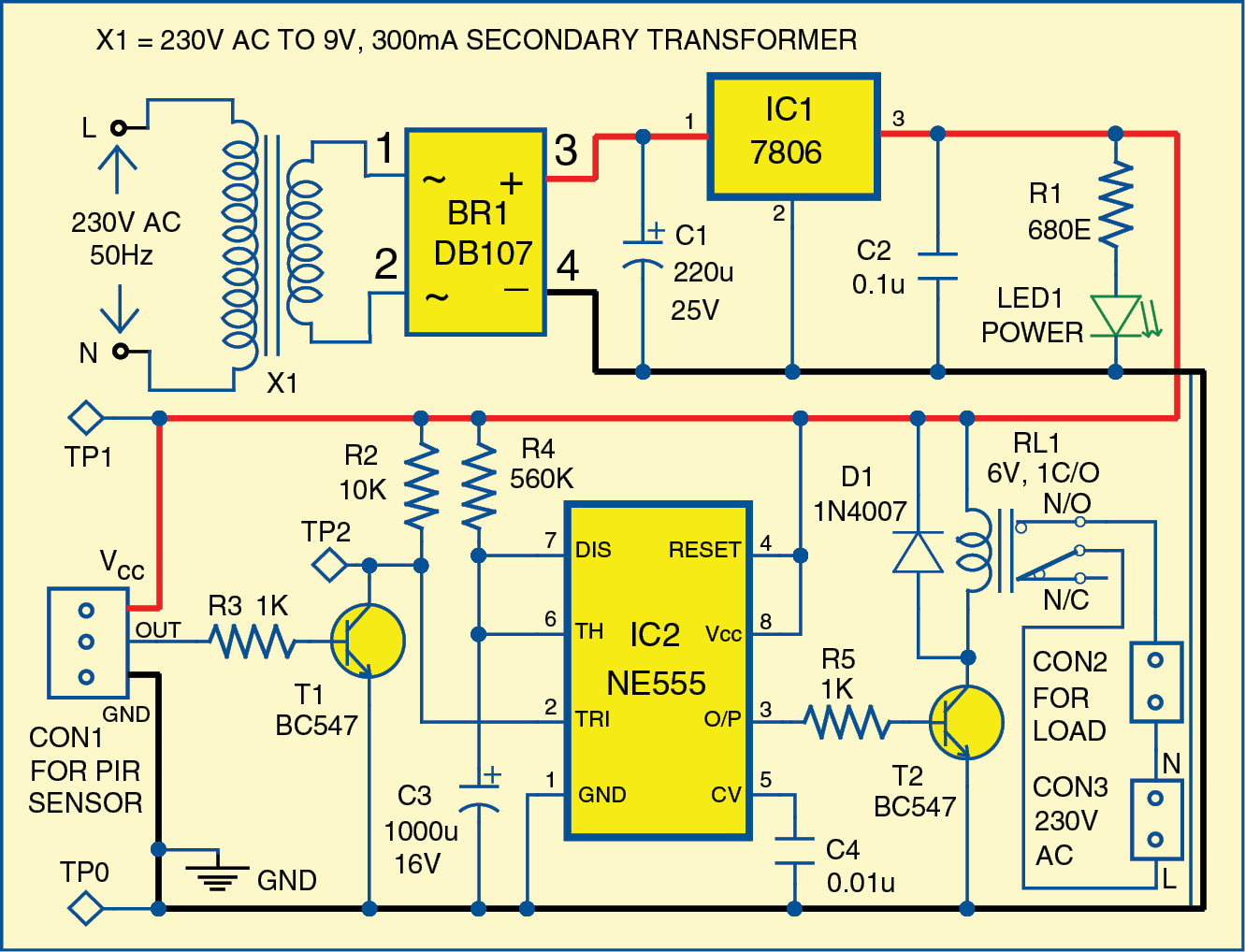
Simple Motion Detector Using NE555 Timer Circuit | Electronic Circuits

EasyEDA - A Cloud based PCB Design Software

555 timer circuits

timer ic 555 tester | Best Engineering Projects
