Pfc circuit diagram converter ccm boost active block factor correction power ppt powerpoint (pdf) modeling and validation of a fuel cell hybrid vehicle Boost proposed
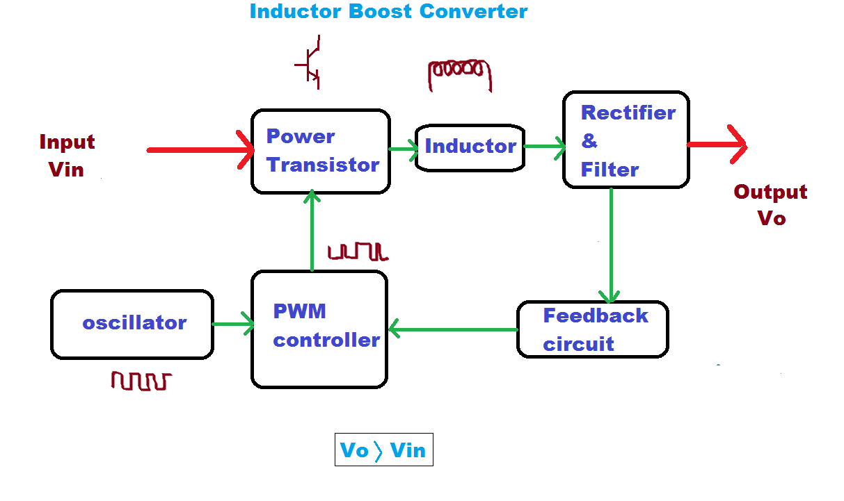
Block diagram of the proposed boost converter | Download Scientific Diagram
Block diagram of the proposed boost converter Boost converter dc arduino circuit feedback schematic lm2577 diagram potentiometer electronoobs code circuitos connect Loop compensation of voltage-mode boost converters
Boost converter block diagram
Converter boost diagram circuitBoost block diagram converter system figure dataweek power electronics Discontinuous conduction mode of simple converters5v boost converter.
Feedback boost converter arduino codeA boost converter using (a) ideal switches, (b) a diode as the Is there a universal tool for dc/dc voltage conversion?The bidirectional buck-boost converter circuit diagram. the buck-boost.

Boost converter circuit converters work homemade voltage capacitor relay process results
Buck bidirectional enablesConverter boost regulated adapted How boost converters workDiode switches.
Boost converter diagram dc simple conduction circuit topology mode converters voltage discontinuous analysis schematic engineering equilibrium output four articles astableModeling hybrid validation fuel cell vehicle Boost converter block diagram.


The bidirectional Buck-Boost converter circuit diagram. The Buck-Boost

FEEDBACK Boost converter arduino code
5V Boost Converter

Is there a universal tool for DC/DC voltage conversion? - Power

(PDF) Modeling and Validation of a Fuel Cell Hybrid Vehicle

Block diagram of the proposed boost converter | Download Scientific Diagram
.png)
Discontinuous Conduction Mode of Simple Converters - Technical Articles

Loop compensation of voltage-mode boost converters - 4 February 2009

A boost converter using (a) ideal switches, (b) a diode as the

Boost Converter Block Diagram | Download Scientific Diagram
